Castings – Reverse Engineer
Project Scope
- Scan the 5 Castings shown.
- Produce Autodesk Inventor 3D CAD Models.
- Produce Autodesk Inventor 2D Drawings.
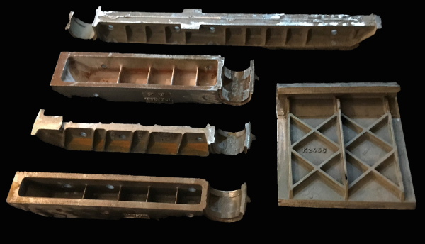
- Scanning the casting will give an accurate model of that specific casting, any imperfections, errors in the casting will be carried into the scan.
- Parts will need to be sprayed with a chalk like powder/developer spray in order dull the shiny surfaces.
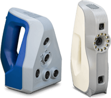
- For this project we would use the Artec Spider Scanner.
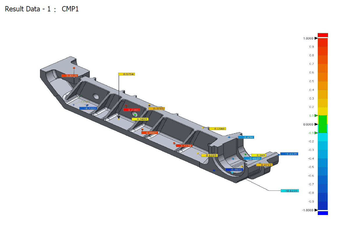
- Due to the condition of the castings, with each STL we will provide an accuracy comparison plot.
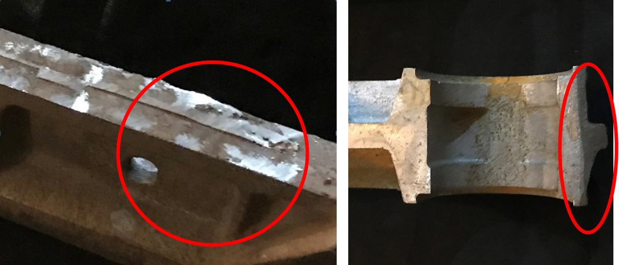
Example of irregular and reflective surfaces and powder/developer spray
Deliverables
- Step 1 – STL File of Scanned Part
- Step 2 – Autodesk Inventor 3D CAD Part and Accuracy Report
- Step 3 – Autodesk Inventor 2D Drawing
Scanning with the Artec Space Spider & Eva into Artec Studio
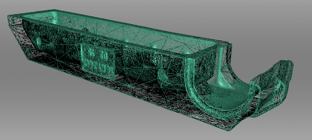
- The output from Artec Studio will be a mesh STL that can then be used to reverse engineer the part
- Due to the nature of the parts, a number of scans will be taken and fused together in the scanning software.
- The STL is a triangulated mesh
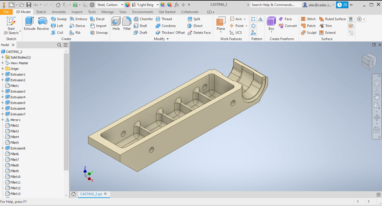
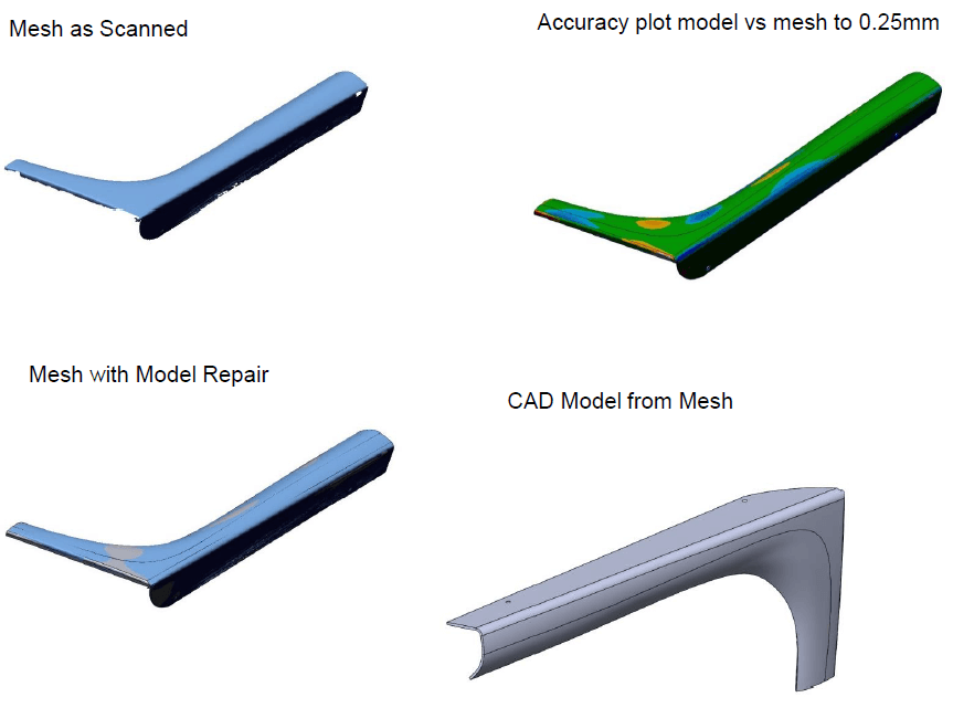
Reverse Engineer in CAD – 3D Parametric Model
A reverse engineering software package can be used to either convert the mesh into a direct solid surface model (non editable) or, as is the case here, the scan data can be reverse engineered in CAD to produce a parametric model, this enables any errors, imperfections in the original part to be corrected.
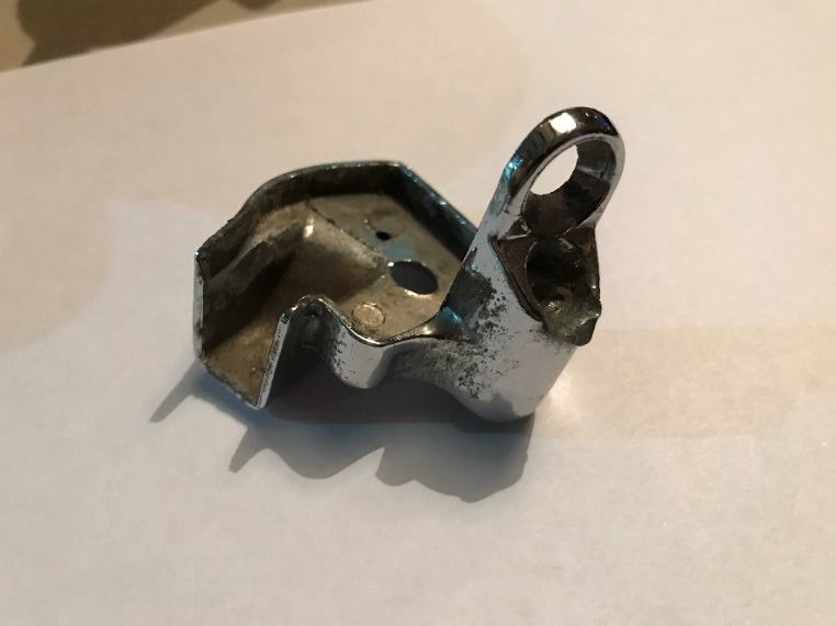
Classic Car Parts
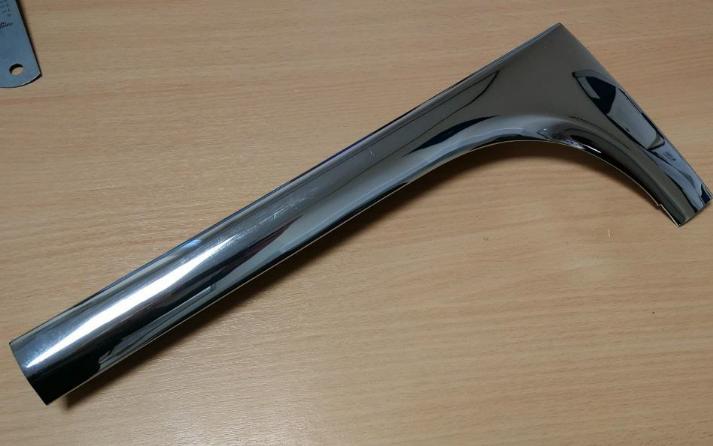
Original Part
Scanned Part & CAD Model

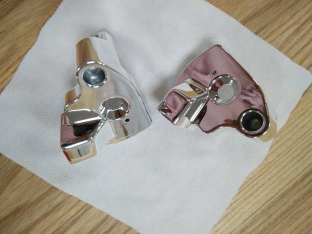
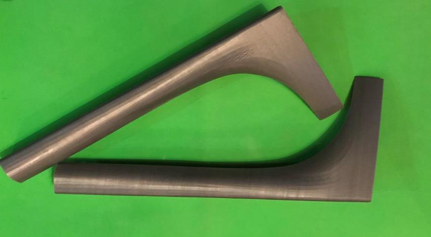
New Parts Machined from CAD Model
Original Part
Scan Data & CAD Models
3D Printed Validation Part from CAD Model
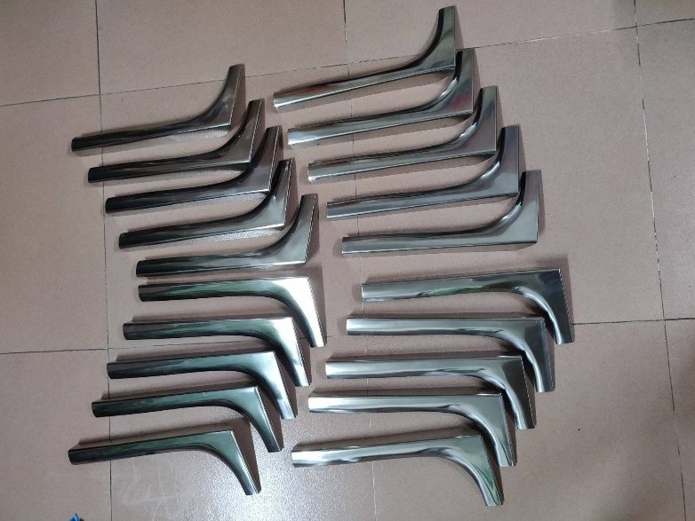
10 Stainless Steel Polished Sets Parts Produced
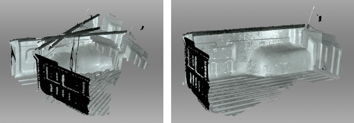
Truck Bed
Initial Scan Data followed by Automatic Alignment
Global Registration & Sharp Fusion followed by Simplification of Mesh
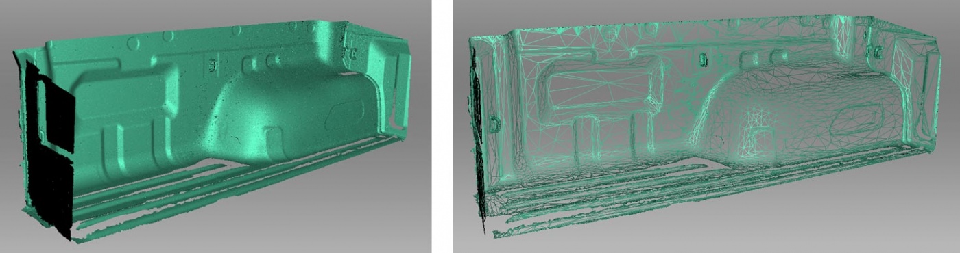
Data exported from Artec Studio in STL format.